Monday, 04. November 2019
Don't you just hate it when someone creates a project like this and you really want to try it yourself. I've been there, the biggest hurdle has always been the PCB. You look at the schematic and no matter how simple or complex it is, you have no idea how to design or create a PCB from scratch. Even if you see a PCB layout, you still have no idea how transfer that onto a circuit board.
Steemit | D.tube | Engrave | Actifit | Exhaust | Endomondo
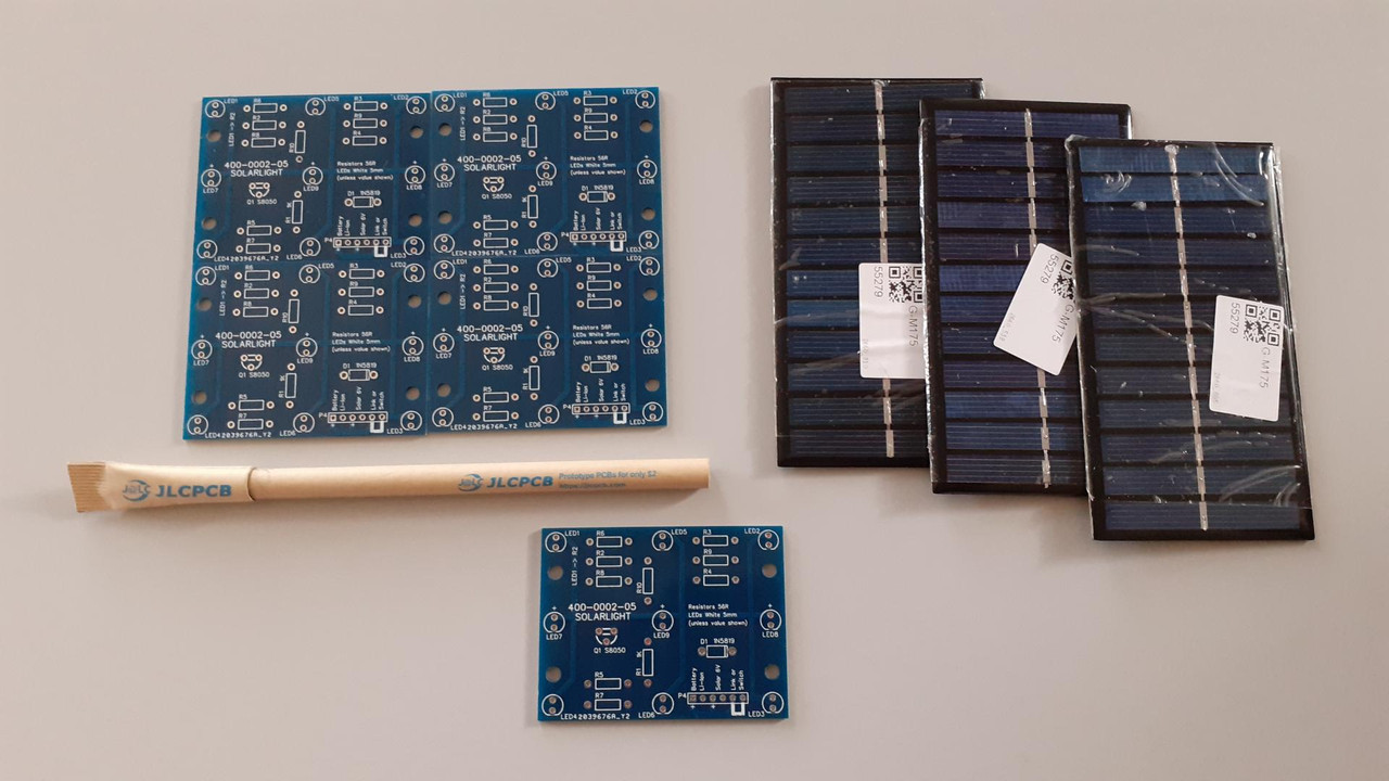
boards from JLCPCB and solar panels
It's Easy and Affordable!
There are a lot of electronic hobbyists like myself out there that design and create PCB's because it really is a lot of fun. The programs we use creates GERBER files:-
Used by the PCB Industry to describe PCB attributes like copper tracks, solder holes, etc. With this information PCB manufacturers can make your board.
We also make these files available to the public because we want others to try out our creations. It is quite possible we encourage other hobbyist out there to realise it is not to hard to achieve their own goals once shown.

Gerber: 400-0002-05
Click on the download button above to get my Gerber file for this board. Note: this particular work is covered by creative commons license (CC BY-SA 3.0) which basically gives you certain freedoms on what you can do. It's pretty simple, you can do what you like. Just credit by adding a link to my steemit page and indicate what changes you made.
Check out the actual license here! CC BY-SA 3.0
Upload this GERBER.zip file to any PCB manufacturer and they would check for compatibility, if all goes well, you would get a quote with a delivery time.
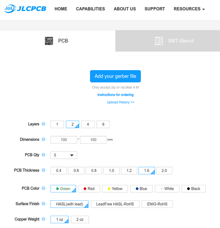
I use JLCPCB
If you need a manufacturer, I recommend JLCPCB , only because I have never used anyone else and had no problems with any boards I had made. Just create an account (it's free) then drag and drop this Gerber.zip onto that blue "Add your gerber file" button.
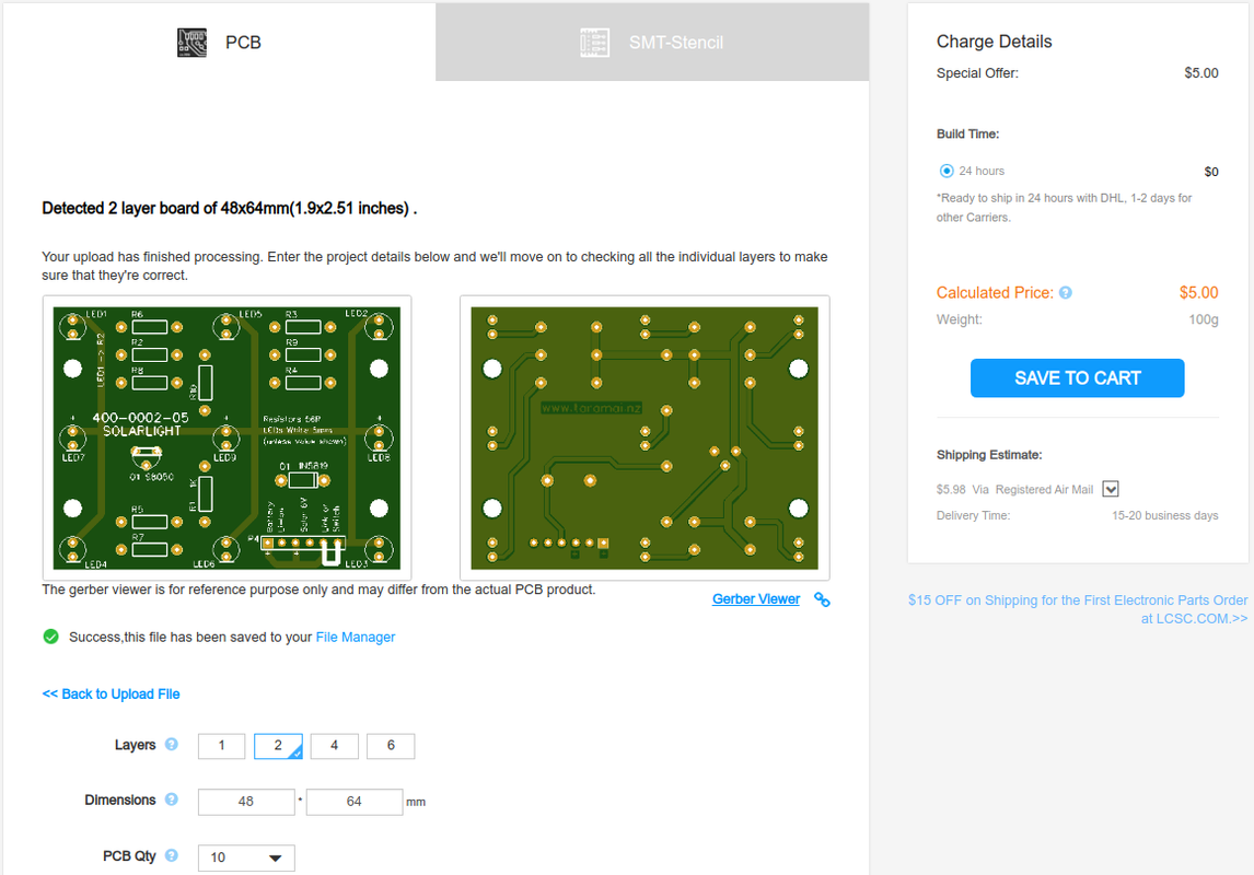
gerber accepted
When you get to this stage you get some really cool options. At the time I sent my order in, you could get blue boards (instead of the default green) made at no extra cost. I also changed the PCB quantity from 5 to 10, I was that confident my PCB design would work just fine.
Moving On
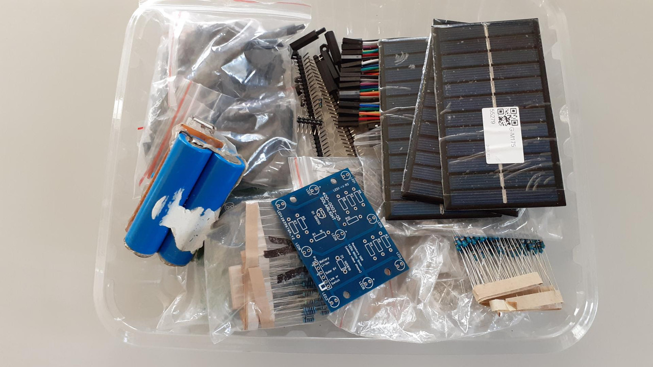
the components
All you need to know is that the component values are written on the PCB itself but I'll make a few notes of it here as well.
- use only 3.7V Li-Ion rechargeable with short-circuit protection battery/s. There are some high capacity mobile phone 2000+ mAH batteries which are perfect for this.
- those 6V .6W solar panels are fine, no point really going any bigger no matter how many batteries in parallel you use.
- any low switching NPN transistor can be used, it's not that crucial. I used a S8050 which is unbelievable cheap, $1.07NZ for 50 free delivery.
BC547 2N3904 2N2222 etc all good, just check on the pin outs.- you don't have to use the 1N5819 shottky diode, it's just more efficient, a cheaper 1N4001 is fine.
- even the resistors can be changed. Initially stick to the original values as shown on the PCB (1x 1k, 9x 56R)
If any Steemian decides to make this, please make a post about it, with a @kiwibloke mention somewhere in the description (or leave a comment here) so that I can find it. I would love to know how well you did at making this and what methods you came up with for the housing/installing part.
Links
- easyeda.com Online PCB Design Tool
- JLCPCB PCB Manufacturer
- EBAY S8050 NPN Transistor
- EBAY 1N5819 Schottky Diode
click on image to take you to my Engrave page
| CRYPTO | Wallet Support |
|---|---|
| ETHEREUM | 0x23Bd7B699383D96513636bf145dCc272a1502076 |
| STEEM | 0x4493de75192e5210091c71506465E31BF5038338 |
| token BAT | 0x6fE7EC6B8bB98210468a15B3235abC80edB70b3d |

click on image to take you to my Steemit page
- with every post comes experience, as we all strive to do better.
- upvote to 80% voting mana, let's encourage and inspire each other.